Wall Sconce from an Aluminium Plate
Turning a discarded machined aluminium plate into an entrance wall sconce — designing a 3D-printed body around a found object I couldn't modify, from AI-assisted concept to a print-ready CAD model.
Some objects are too nice to throw away before you know what they’re for. This is the story of one — a machined aluminium plate — becoming the light by my front door.
The problem
A while back I came across a machined aluminium plate: 105 × 135 mm, 6.5 mm thick, its face drilled with a dense, even grid of countersunk holes. It was almost certainly a cast-off from some engineering job, and I have no idea what it originally did. That didn’t matter. I liked how it looked — the weight of it, the regularity of the grid, the way light caught the countersinks — and I kept it.
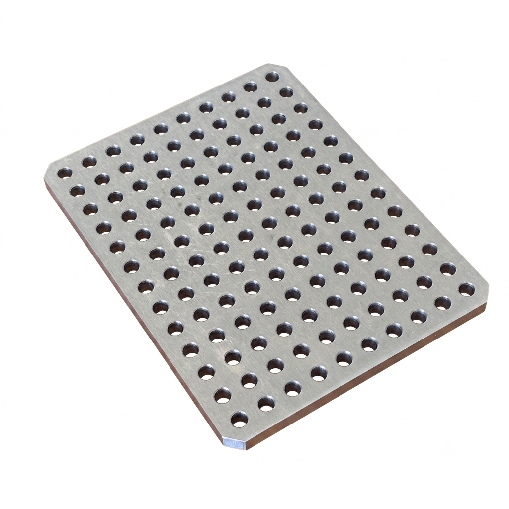
It sat in my pile of maybe-someday parts for a few weeks. In parallel I had a real, small problem: the entrance to my home needed a wall sconce. At some point the two collided — the plate could be the sconce, or at least its face. That reframed the project into the constraint that shaped everything after it: design a light fixture around an object I found rather than made, and can’t machine further. The plate’s dimensions, its hole pattern, its flatness — all fixed inputs. My job was to build the rest of the fixture to serve them.
The idea
The perforated face suggested its own function. Backlit and tilted up, that grid of holes turns the plate into an emitter — a wall-wash that throws light up the wall above the door, rather than a task light aimed at a visitor’s eyes. So the concept settled quickly: the aluminium plate as a tilted, light-emitting face, carried by a 3D-printed body that holds the bulb, hides the wiring, and mounts to the wall.
Getting from “nice plate” to a specific, buildable form is where I leaned on AI. I used a large language model as a sounding board for the concept and an image model to sketch variations — proportions, how the body should cradle the plate, the mounting angle. That loop is genuinely useful for the early, fuzzy part of industrial design: it’s fast at throwing out plausible silhouettes to react to, which beats staring at a blank sketchbook. What it produces is a mood and a direction, not a manufacturable object — the renders don’t know about wall thicknesses, socket clearances, or print orientation. So I treated the output as a reference to converge on, then redrew the real geometry myself in CAD.
A few habits made the loop work harder. I often asked for several distinct options packed into a single image — partly to save generations, mostly because forcing the options to share a frame pushes the model to make them genuinely different from each other instead of collapsing on one safe answer. I also had the sconce staged in a room rather than floated on a blank backdrop, so each render answers the question that actually matters — does the fixture suit the atmosphere of the space it lights? One thing consistently fought back: the single part of the design that is physically fixed, the aluminium plate, was the hardest thing to keep fixed — in several renders below the model quietly re-grids, stretches, or outright replaces it. And since the body is to be 3D printed — a process that will happily produce almost any shape — I deliberately let the loop run in some very creative directions, folded and wavy and organic, to see how far the form could go before pulling it back. The slideshow opens on the direction I chose, then runs through the exploration in roughly the order it took:
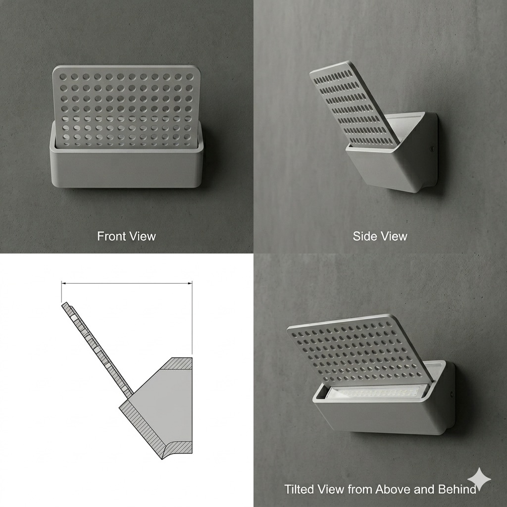
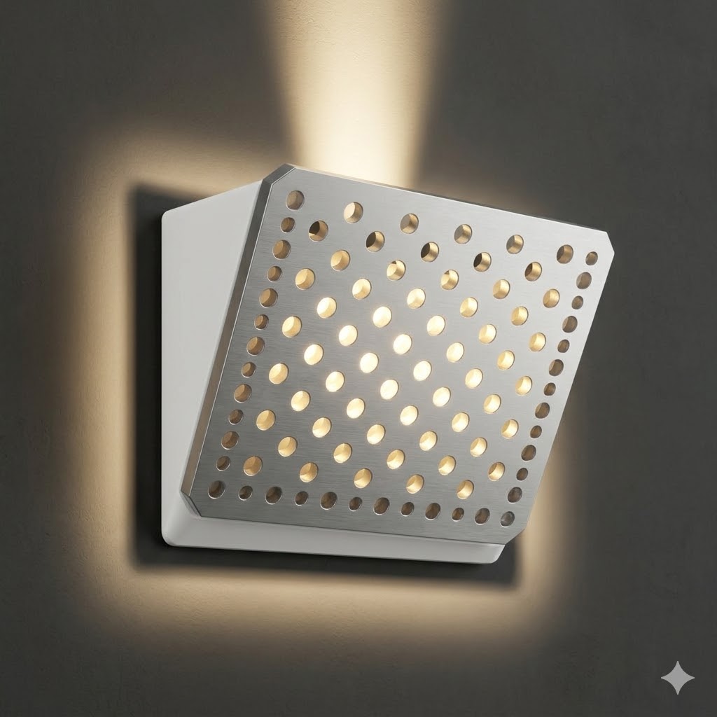
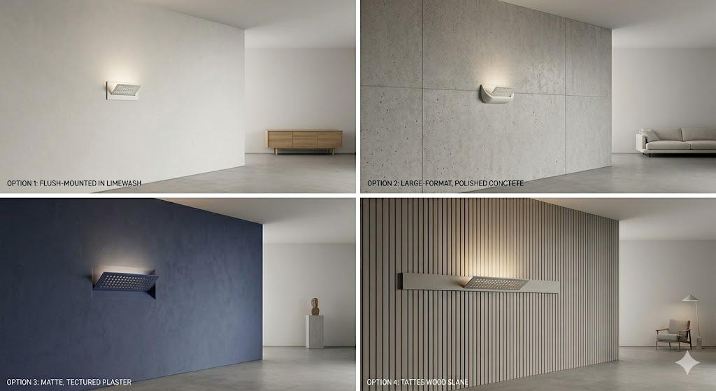
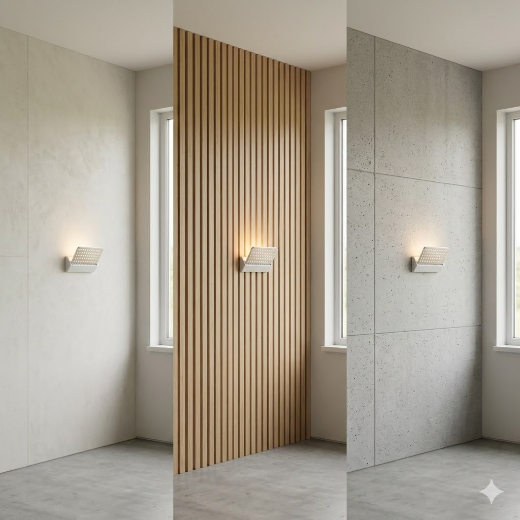
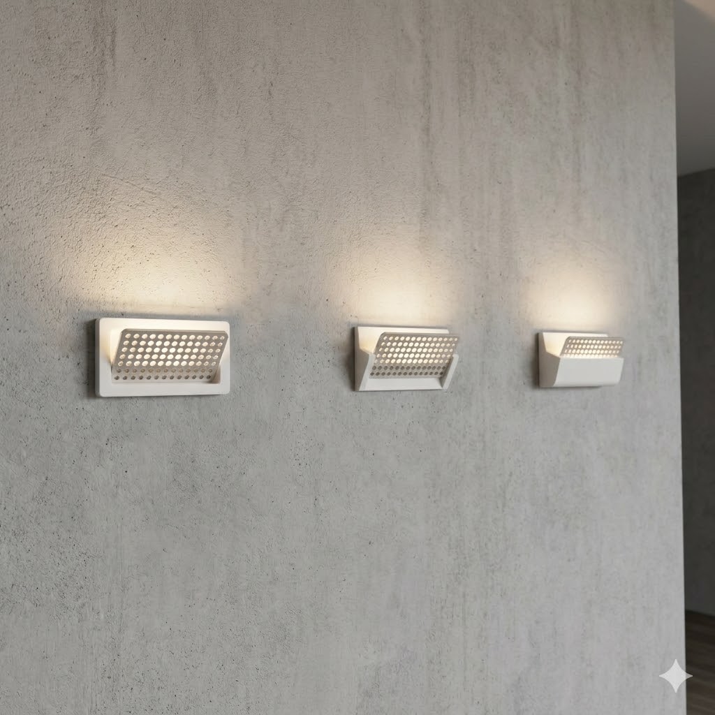
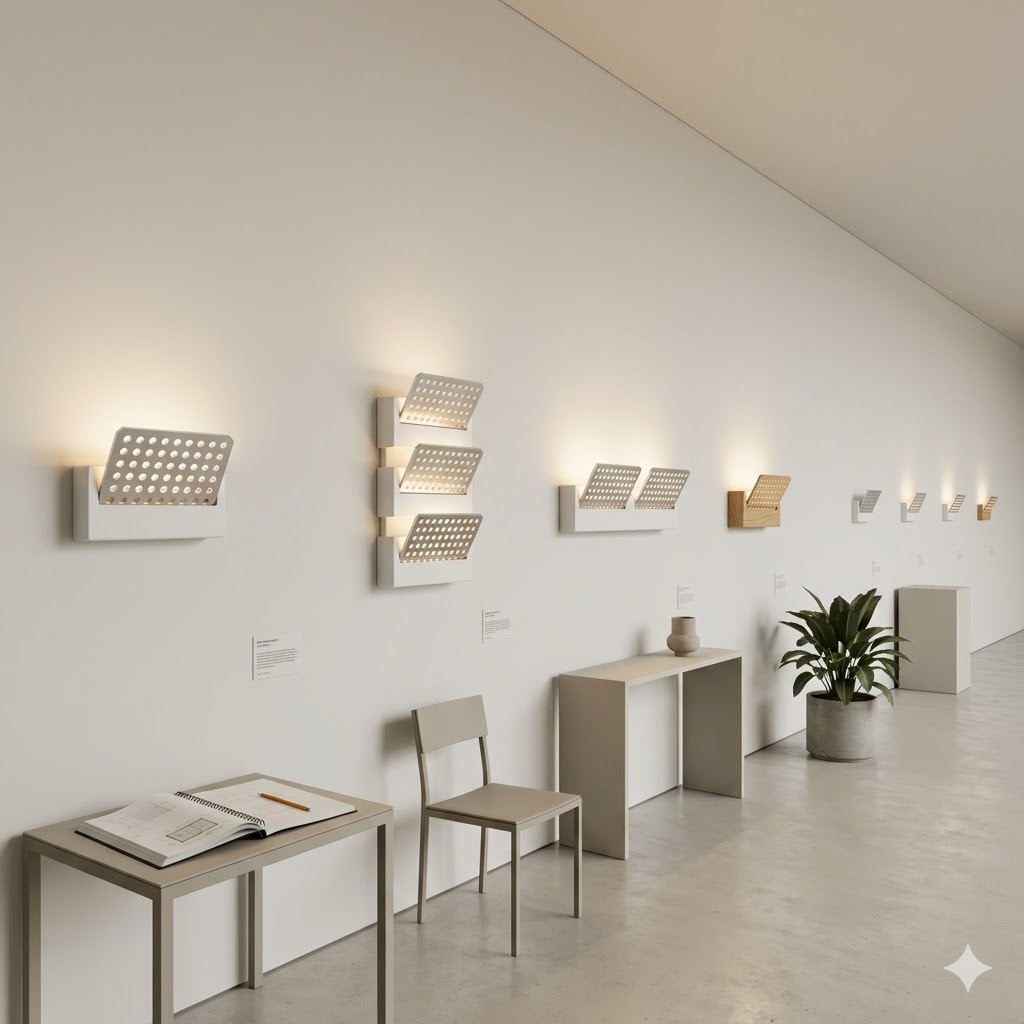
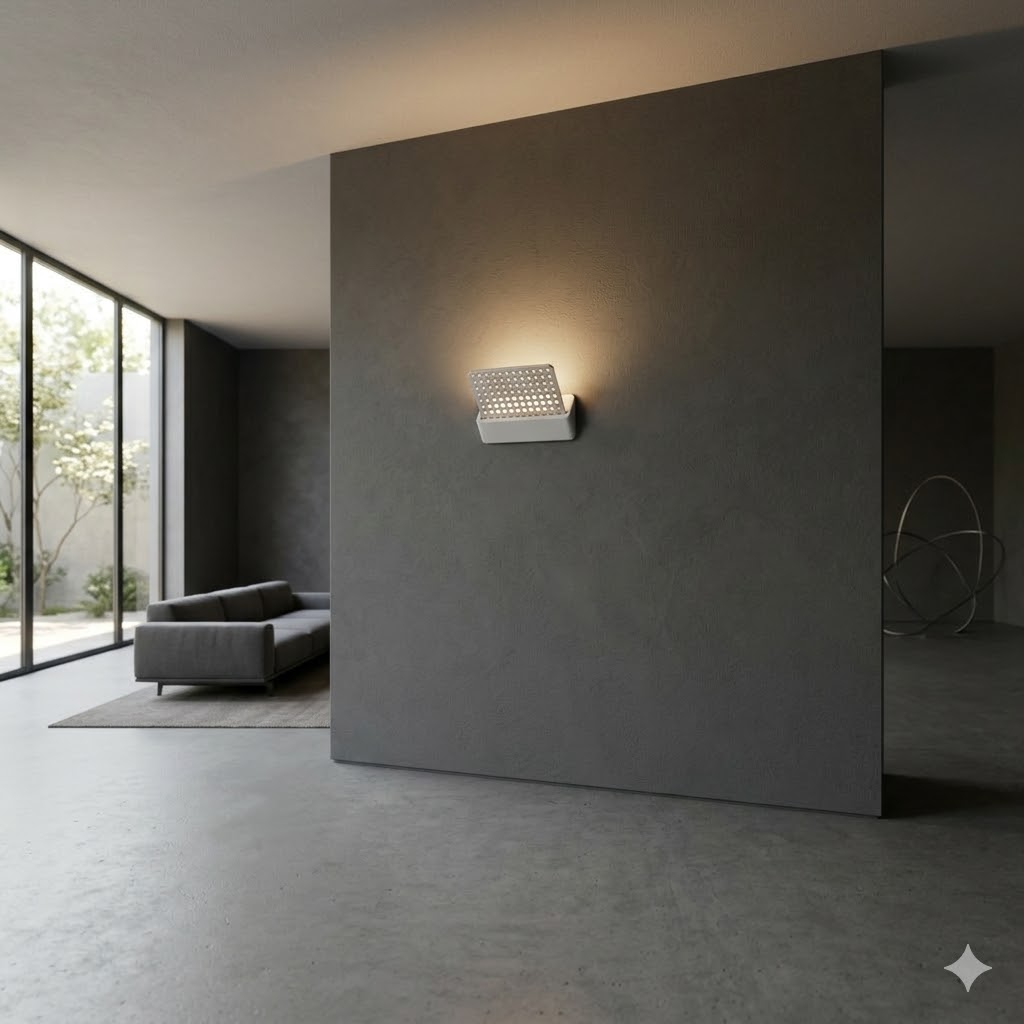
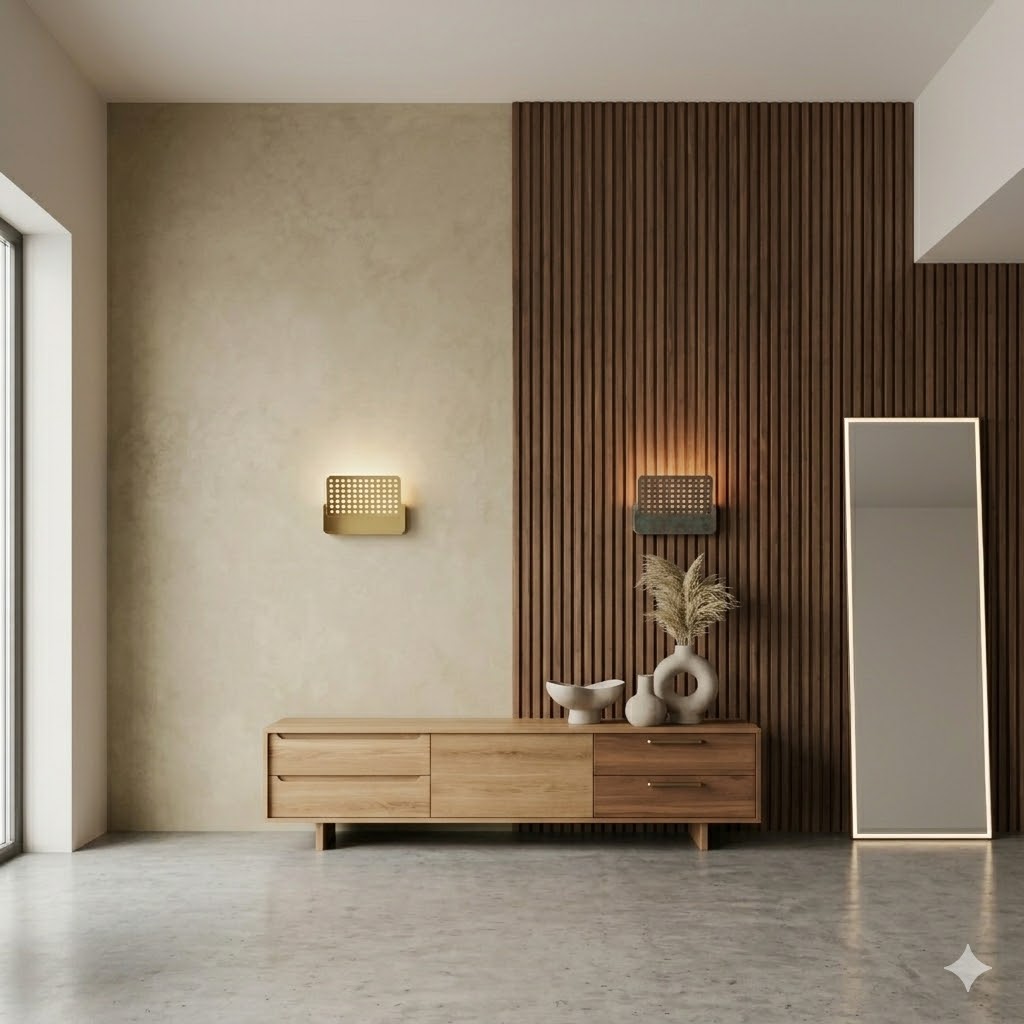
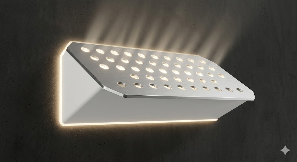
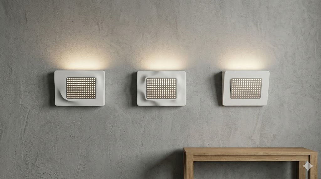
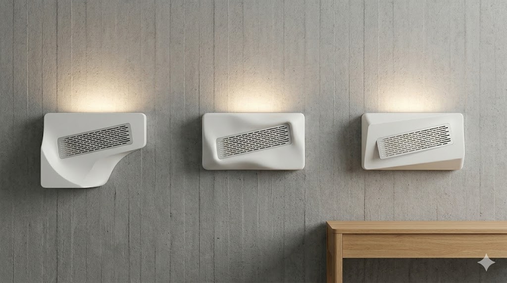
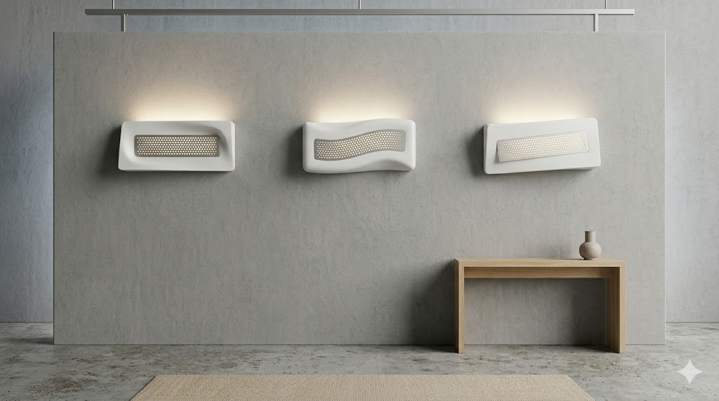
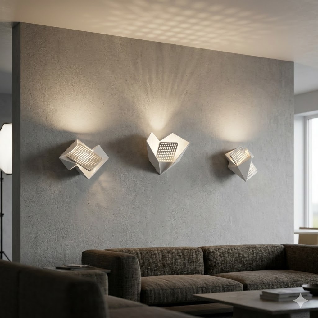
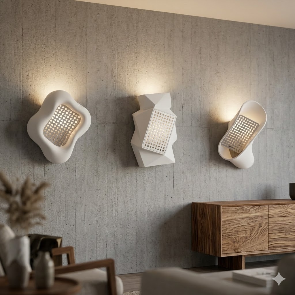 [chosen]
 Where the loop landed — the chosen direction pinned down in front, side, section, and tilted views. This is the reference the CAD model below was drawn against. Everything after this slide is the exploration that led here.
How it works
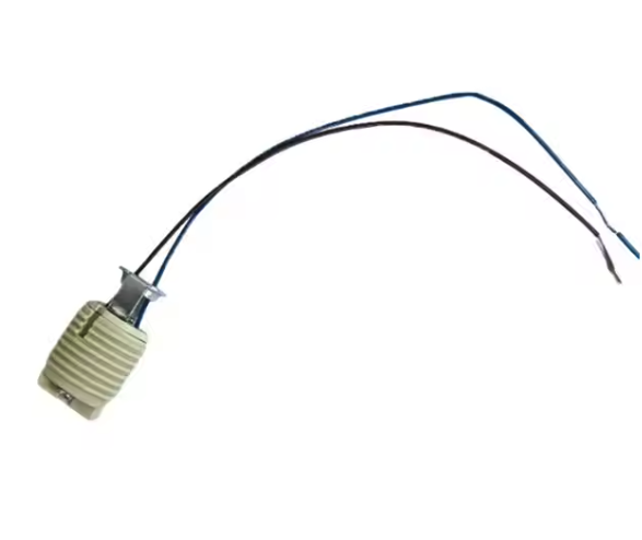
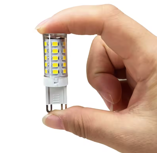
The light source is deliberately ordinary and replaceable: a G9 LED bulb in a G9 ceramic socket, both cheap and stocked everywhere, so a burnt-out bulb is a 30-second swap rather than a soldering job.
Around those parts is the printed body — roughly 150 × 90 × 120 mm — a wedge that stands off the wall and presents the plate at an upward angle. Here is the current CAD model. Drag to rotate it freely, scroll to zoom, and use reset view to return to the framed pose. The explode slider pulls the assembly apart into its four parts — plate, bulb, mount, body — along the directions authored in the CAD exploded view, and bulb light dims the room and switches the G9 on, casting real shadows so you can see how the light actually leaves the fixture:
loading model…
The current CAD assembly. Explode separates the aluminium plate, G9 bulb, wall mount, and printed body; bulb light simulates the lit fixture — watch the glow through the plate's perforations. Rendered in the site's grayscale — the intended print is a matte white/light-gray.
Several sub-problems have to be solved inside this body rather than bolted on afterward, and they’re the parts still being worked out: capturing the G9 socket so the bulb sits at the right depth behind the plate; routing the mains cable up from the wall and into the body without a visible gland; anchoring the whole thing to the wall through a hidden bracket; and — the one that most affects how it actually looks lit — scattering the light so the face glows evenly instead of showing a bright hotspot through the holes (the bulb light slider above gives a feel for it: a bare G9 close behind the plate). The plan for that last one is a two-layer stack behind the plate: a reflective aluminium sheet with an embossed pattern to bounce and break up the beam, and an opal frosted acrylic diffuser to even it out before it reaches the perforations. The exact geometry of each of these is still TBD, and I’ll document them here as they’re resolved.
Results
As of now the project is an exploration: the CAD model above is finished and print-ready, but nothing has been printed or wired yet, so I can’t yet show you the thing switched on — which is the honest state of it. What exists is the design decision that matters (build the fixture around the found plate) and a complete model that commits to it.
The build itself was recorded — here’s a timelapse of modelling the body around the plate:
Next steps are to print the body, resolve the socket capture and cable routing against a real printed part, and dial in the diffuser stack until the lit face looks the way the plate deserves. I’ll update this page — and its status — as those land.